
973 228 164

Support Phone Number

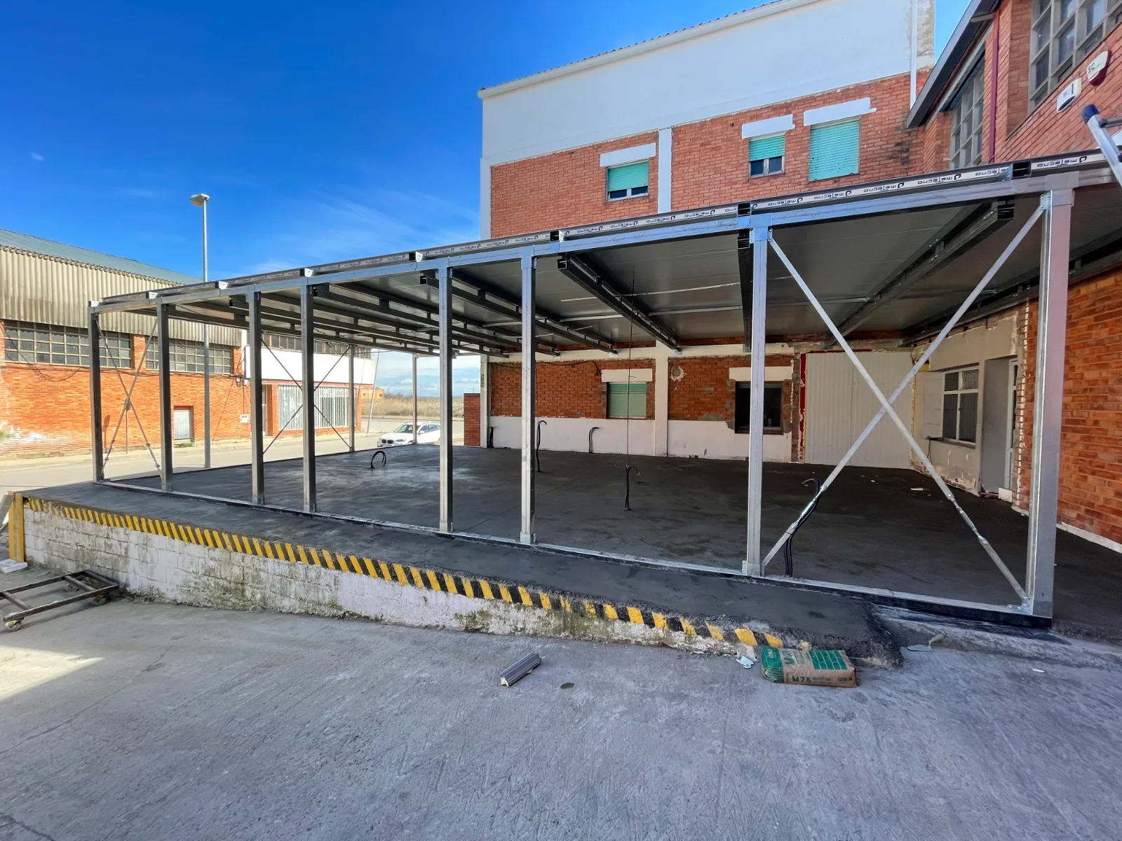
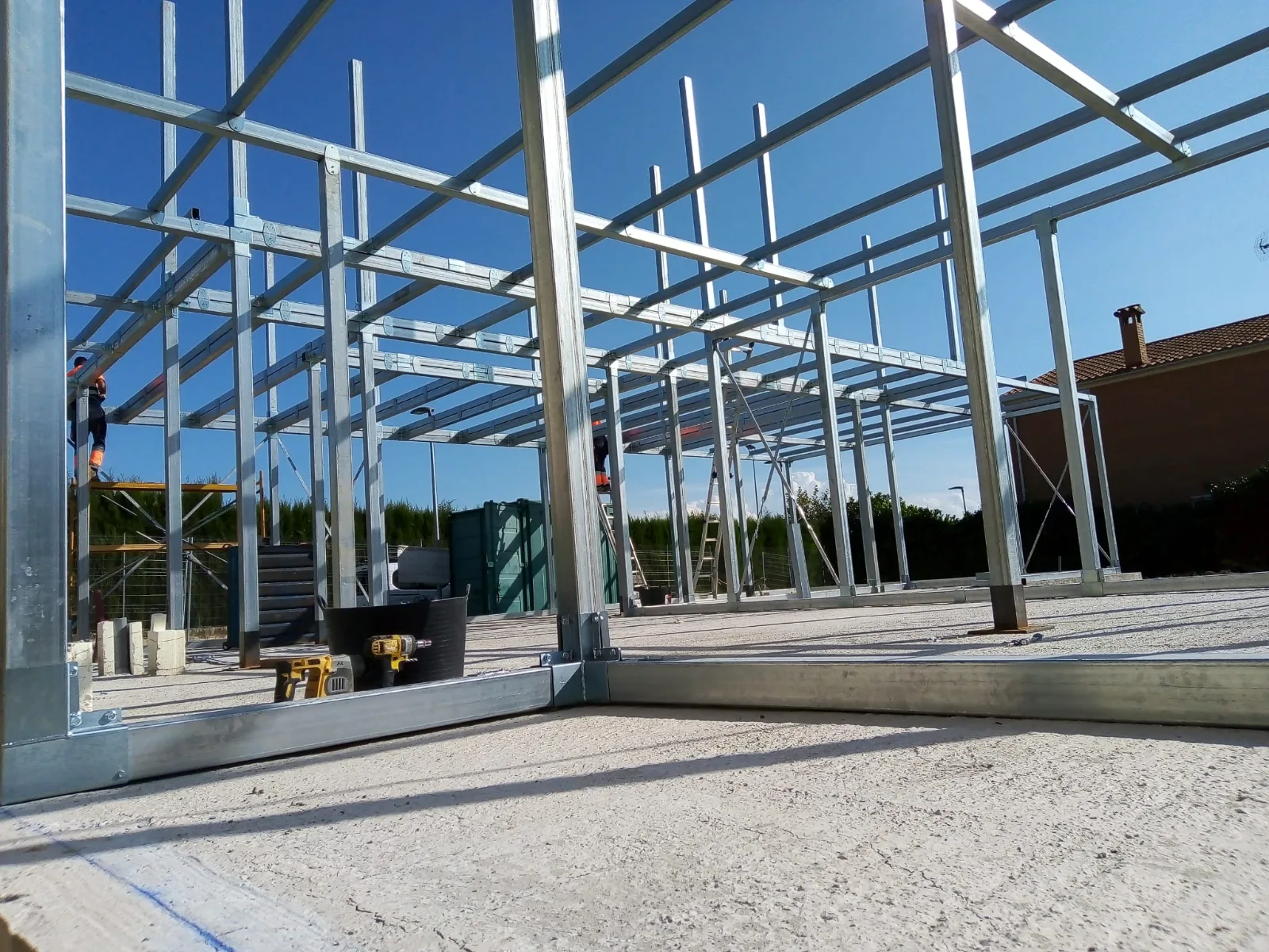
Starmodul bolted steel structure: building under construction

Technical data · Tests and calculation

StarModul joint strength: data for structural design

Load table of the 1010 series joints tested in the laboratory, materials, indicative spans and real calculation examples for your project engineer.

14joints tested to failure
65 kNtension on joint 1010-21
2017–2018tests at the LERMA laboratory (UPC)
8.8grade of all bolts

For the engineer

Data for the design of your structure

This page gathers the data we send with our quotes for the structural design of a bolted steel structure with the StarModul system: materials, reference loads, the strength of the bolted joints of the 1010 series (tension, compression, shear and bending moments), the reinforcing fasteners, indicative spans, bracing and the failure tests.
Important: the joint values are laboratory test results (LERMA laboratory of the Universitat Politècnica de Catalunya, 2017–2018) with 100×100×2 mm tube, the thinnest wall. They are indicative values, not design resistances. Every project must be calculated by an engineer under the applicable building codes; StarModul can quote the structural calculation for you.
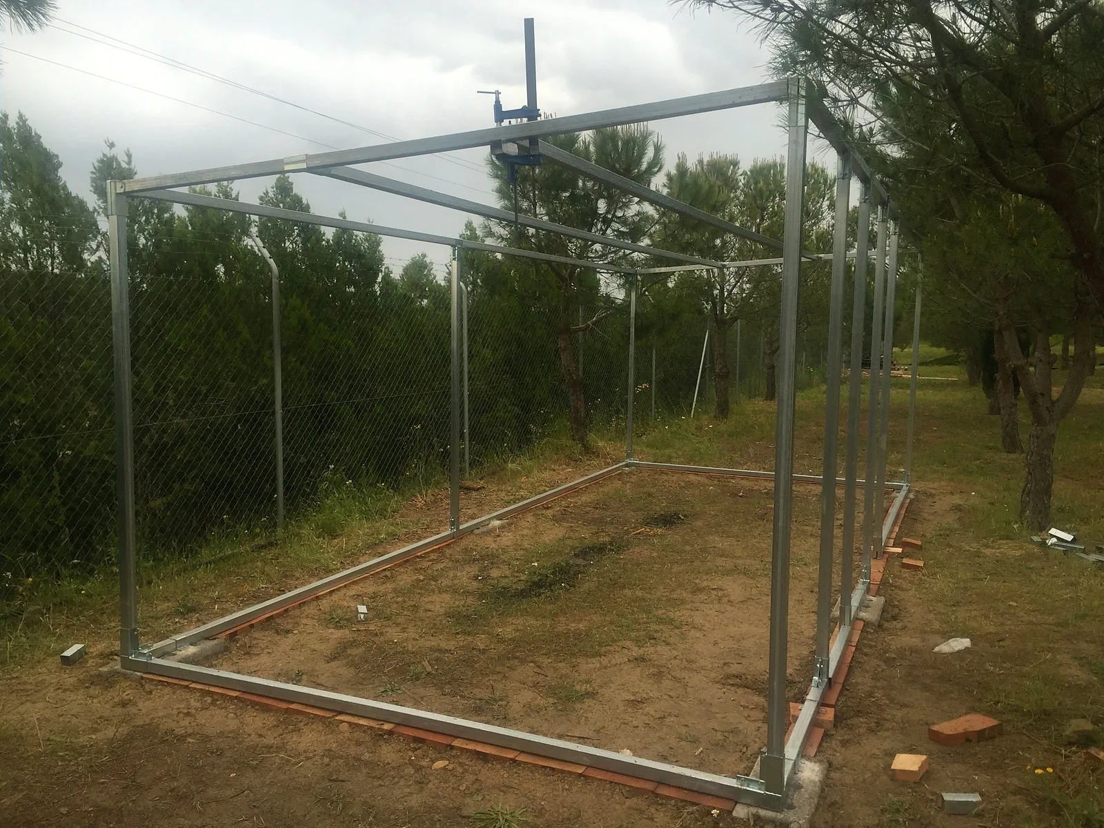
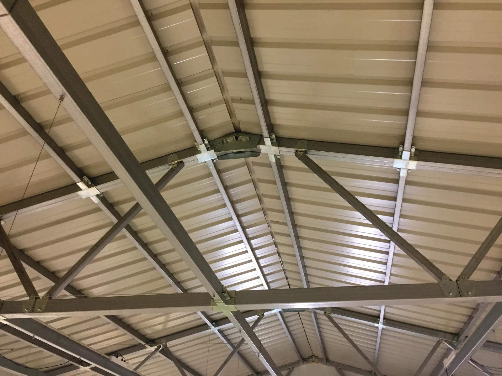
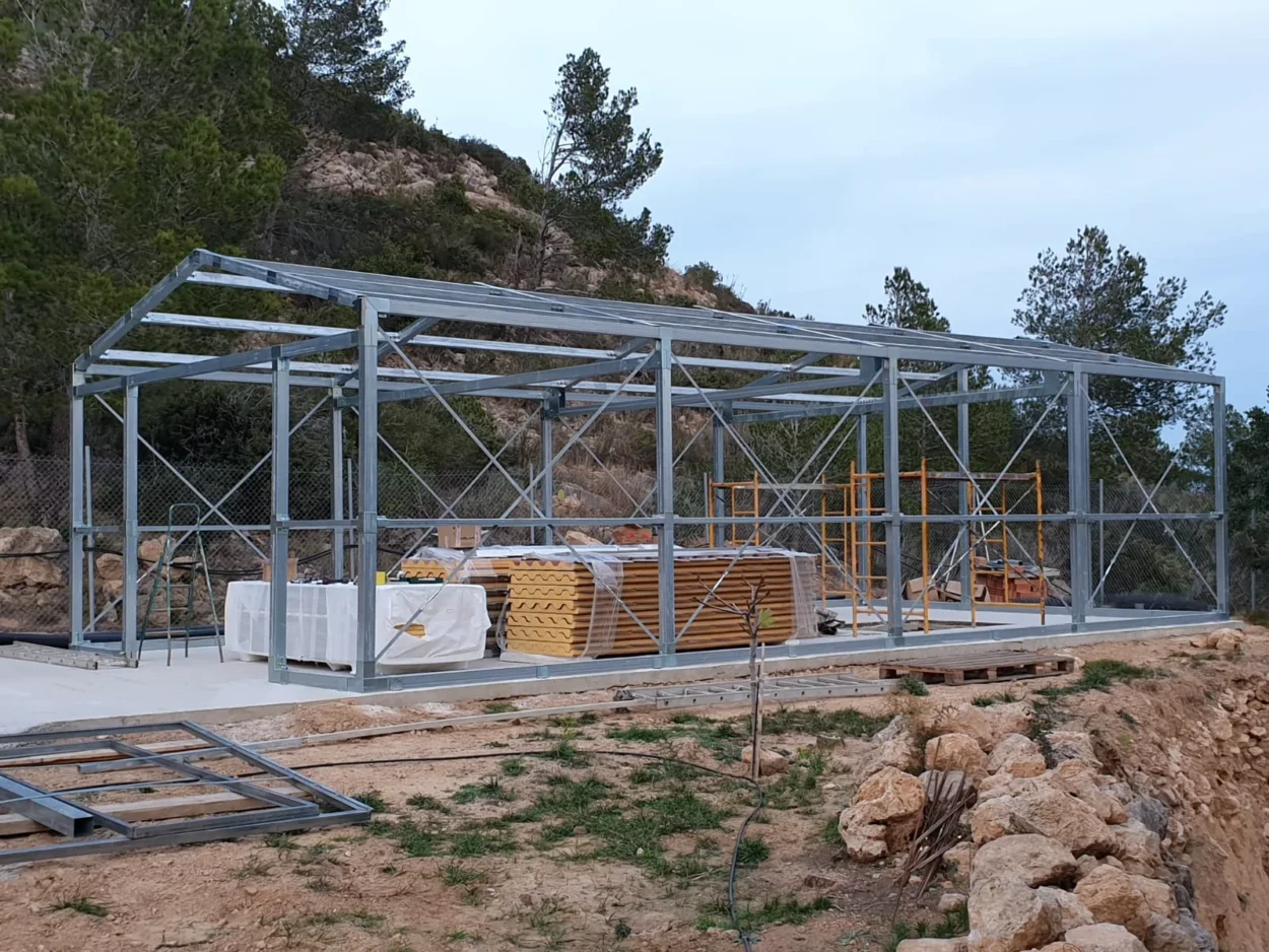
Starmodul bolted steel structure: assembled structure (faura)

General aspects and materials

Structural design of a StarModul steel structure

The structure is analysed as a single 3D model. Secondary door and window sub-frames are left out of the global model (on the safe side) unless they are needed to place bracing such as X-bracing. The building is designed to meet the Spanish Building Code (CTE) and the structural and concrete standards in force.

Materials used in the calculation

ElementMaterialfy (N/mm²)fu (N/mm²)Standard
Hollow sections 100×2 and 100×3S250GD+Z250330UNE-EN 10346
Cold-formed omega sectionsS350GD+Z350420UNE-EN 10346
Hot-rolled sections, bracing and platesS275JR275430UNE-EN 10025-2
Ordinary boltsGrade 8.8640800UNE-EN ISO 898-1

Partial factors: 1.00; 1.00; 1.25. Data from the document “Basic data for structural design with the StarModul system”. These are design values from the calculation reports, not certificate values: to stay on the safe side, the design of each building takes a grade for the tube equal to or lower than the certified grade; the batch certificate gives the measured values shown in the next table.

Certificates of the 100×100 mm structural tube

TubeSteel and coatingStandardCertificateRe (MPa)Rm (MPa)A (%)
100×100×2 mm, 12 mS350GD + ZM310 (zinc-magnesium)EN 10219-1/-2, CE marked3.1 EN 10204 (Feb 2026)48751121
100×100×3 mm, 12 mS350GD + ZM310 (zinc-magnesium)EN 10219-1/-2, CE marked3.1 EN 10204 (Jan 2026)467–549516–61521–26

Re: yield strength; Rm: tensile strength; A: elongation. Values measured in the tensile test of the certified bars (minimum and maximum). 2, 3 and

Joints

3 mm steel sheet (DD11, EN 10111; 3.1 certificate: Re 246 MPa, Rm 356 MPa) with electrolytic zinc plating and trivalent passivation, free of chromium VI. CE marking to harmonised standard EN 1090-1 (system 2+, EXC2), factory production control certificate 0370-CPR-2637. Reaction to fire A1.

Reference loads

Permanent loads considered

Self-weights: reinforced concrete 25.00 kN/m³; steel 78.50 kN/m³. The system’s reference permanent loads are:

LoadValueBreakdown (kN/m²)
G1 · Upper floor slab2.50 kN/m²100 mm panel 0.125 · 10 mm cement board 0.120 · flooring 0.305 · underfloor-heating screed 0.950 · partitions 1.000 · omegas (in the software)
G2 · Terrace2.50 kN/m²100 mm panel 0.125 · cement board 0.120 · flooring 0.305 · sloping screed 1.950
G3 · Light roof0.40 kN/m²100 mm panel 0.125 · 35 mm panel 0.100 · secondary slope structure 0.125 · suspended ceiling 0.050
G4 · Façade0.35 kN/m²100 mm panel 0.125 · external finish 0.225

Imposed, snow, wind and seismic loads depend on the site and are set by the engineer for each project.

1010 series joints (100×100 tube)

Bolted joint strength: load table

Summary strength values for each joint type, obtained in failure tests at the LERMA laboratory (UPC) with 2 mm tube. Forces in kN; bending moments in kN·m.

JointNode typeTension (kN)Compression (kN)Shear (kN)My (kN·m)Mz (kN·m)
1010-01Corner node, 3 arms at 90°17.9034.6324.752.302.15
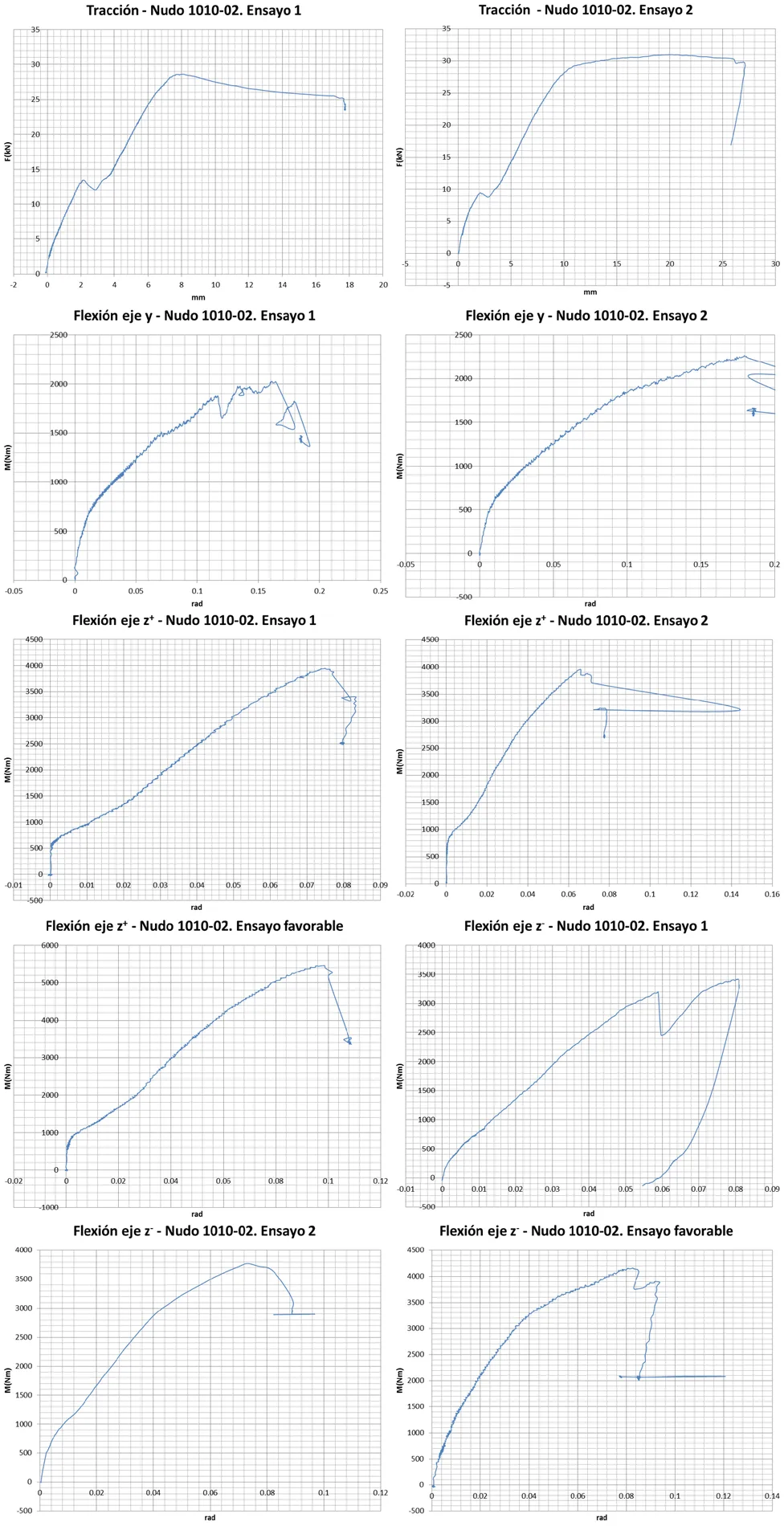
1010-02L node, 2 arms at 90°25.00––3.001.70
1010-032 arms at 90° + 1 hinged19.46––––
1010-05T node20.26–28.971.454.20
1010-064-arm node at 90°21.10–23.111.072.98
1010-073 arms at 90° + 1 hinged21.99––––
1010-11Cross node, 4 arms––22.182.883.73
1010-13Column base anchor to a surface20.00––4.001.20
1010-14Hinged anchor to a surface25.00––––
1010-15Tube fixing to a parallel surface–––2.002.80
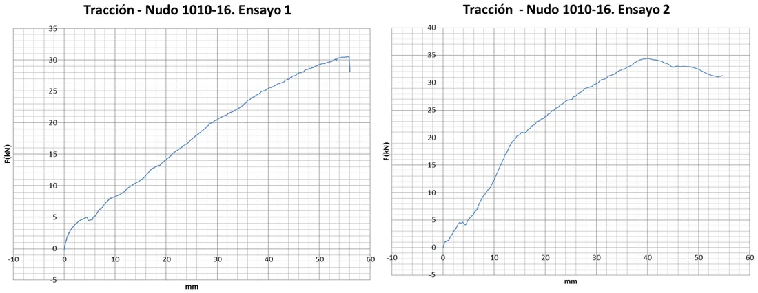
1010-16Hinged crossing of two tubes30.00––––
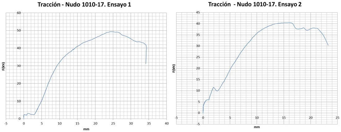
1010-17Hinged T joint (bracing)35.00––––
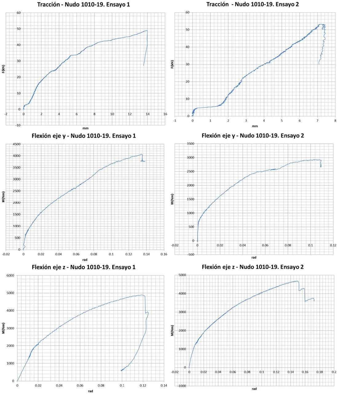
1010-19120° node (ridge)45.00––2.504.40
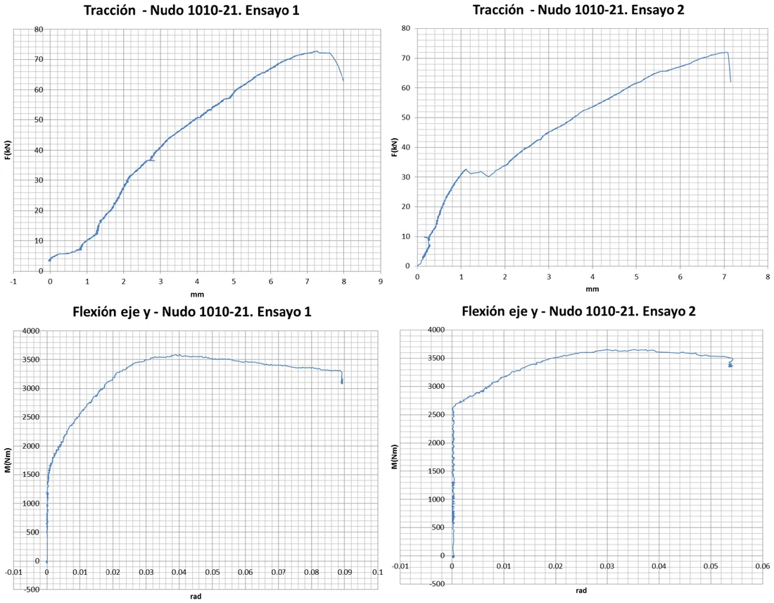
1010-21180° splice of 2 tubes65.00––3.20–

“–”: not tested. Indicative laboratory values; they are not design resistances. In many tests failure occurred in the tube (local buckling or tearing), not in the joint. With 3 or 4 mm tube the capacity of the assembly increases, but each case is checked in the calculation.

The joints in the table, in 3D

Drag each part to rotate it. Tap the reference to open its product page.

1010-01Corner node, 3 arms at 90°
1010-02L node, 2 arms at 90°
1010-032 arms at 90° + 1 hinged
1010-05T node
1010-064-arm node at 90°
1010-073 arms at 90° + 1 hinged
1010-11Cross node, 4 arms
1010-13Column base anchor to a surface
1010-14Hinged anchor to a surface
1010-15Tube fixing to a parallel surface
1010-16Hinged crossing of two tubes
1010-17Hinged T joint (bracing)
1010-19120° node (ridge)
1010-21180° splice of 2 tubes
Failure load of each specimen (2017–2018 tests)
JointTestSpecimen 1Specimen 2Failure mode
1010-01Tension19.42 kN17.90 kNdeformation of the joint
1010-01Compression34.63 kN35.30 kNlocal buckling of the tube
1010-01Bending My2.43 kN·m2.29 kN·mdeformation of the joint
1010-01Bending Mz2.60 kN·m2.14 kN·mdeformation of the joint
1010-01Shear Ty / Tz32.29 / 24.75 kN27.14 / 26.56 kNlocal buckling of the tube
1010-02Tension28.61 kN30.98 kNdeformation of the tube
1010-02Bending My2.03 kN·m2.27 kN·mbolt and deformation
1010-02Bending Mz+ / Mz−3.95 / 3.42 kN·m3.95 / 3.77 kN·mdeformation of the node
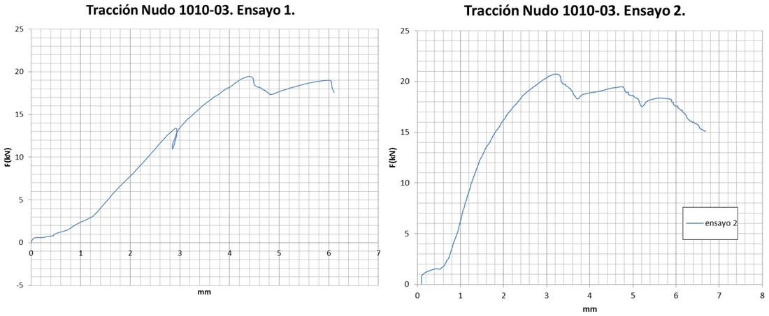
1010-03Tension (hinged arm)19.46 kN20.73 kNdeformation of the joint
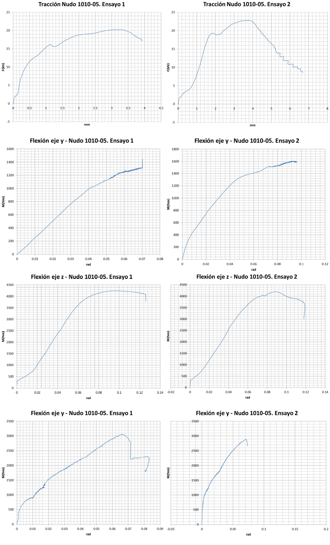
1010-05Tension20.26 kN22.81 kNdeformation of the joint
1010-05Bending My (2017 / 2018)1.45 / 3.06 kN·m1.61 / 2.89 kN·mdeformation of the joint
1010-05Bending Mz4.24 kN·m4.20 kN·mdeformation of the joint
1010-05Shear Ty / Tz30.31 / 34.10 kN28.97 / 34.06 kNlocal buckling of the tube
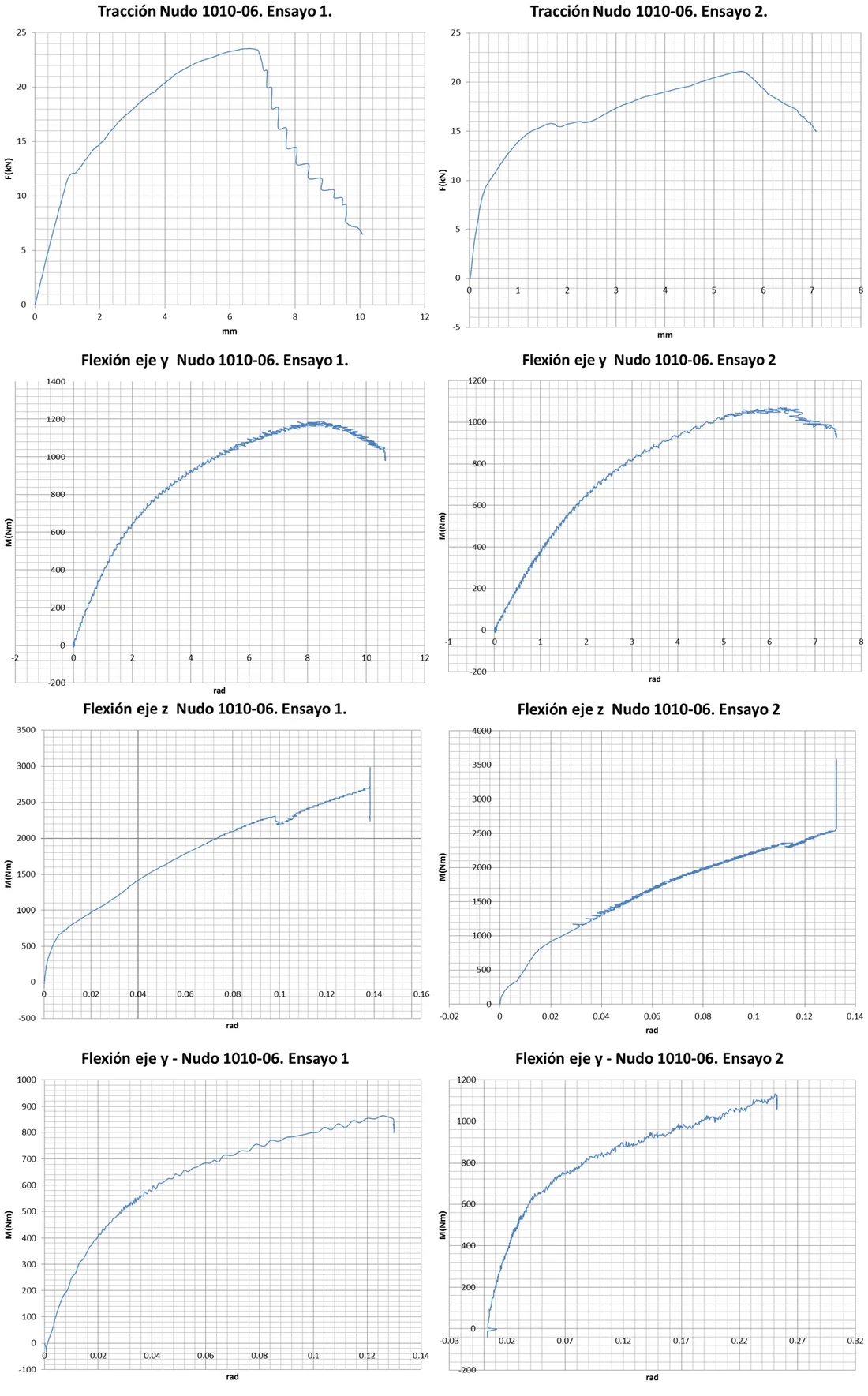
1010-06Tension23.55 kN21.10 kNdeformation of the joint
1010-06Bending My (2017 / 2018)1.19 / 0.86 kN·m1.07 / 1.13 kN·mdeformation
1010-06Bending Mz2.99 kN·m3.59 kN·mdeformation
1010-06Shear Ty / Tz23.11 / 25.55 kN24.35 / 34.04 kNlocal buckling of the tube
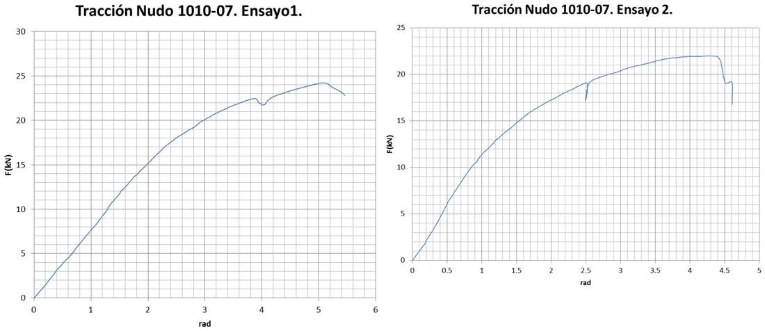
1010-07Tension (hinged arm)24.22 kN21.99 kNdeformation of the joint
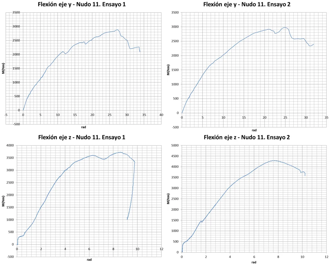
1010-11Bending My / Mz2.89 / 3.73 kN·m2.98 / 4.29 kN·mdeformation
1010-11Shear Ty23.12 kN22.18 kNlocal buckling of the tube
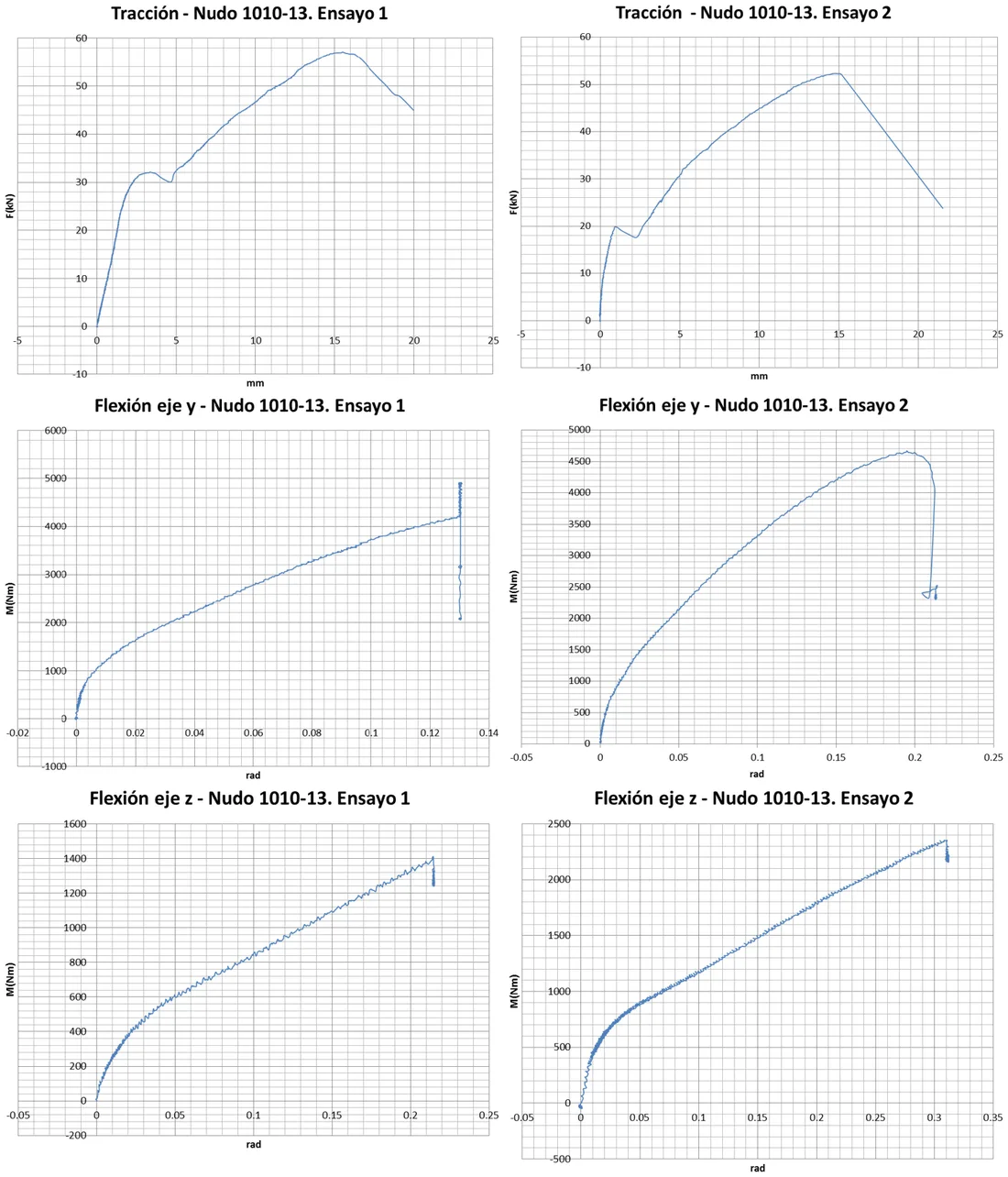
1010-13Tension57.12 kN52.32 kNdeformation of the plate
1010-13Bending My / Mz4.92 / 1.41 kN·m4.67 / 2.36 kN·mdeformation of the plate
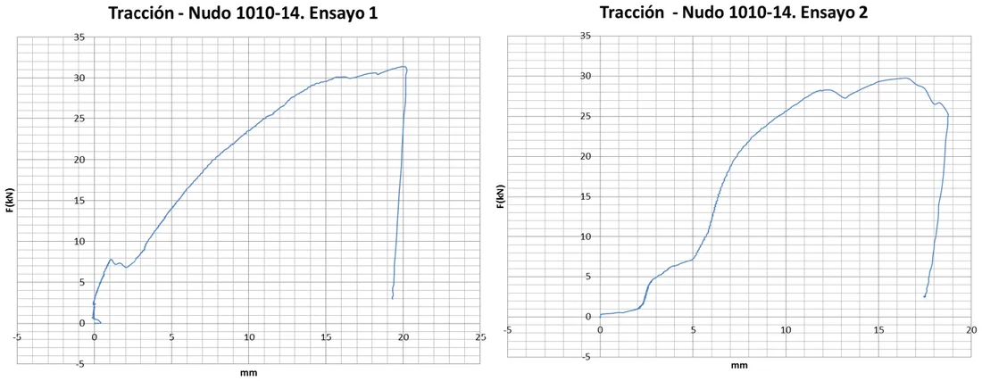
1010-14Tension31.36 kN29.78 kNtearing of the tube
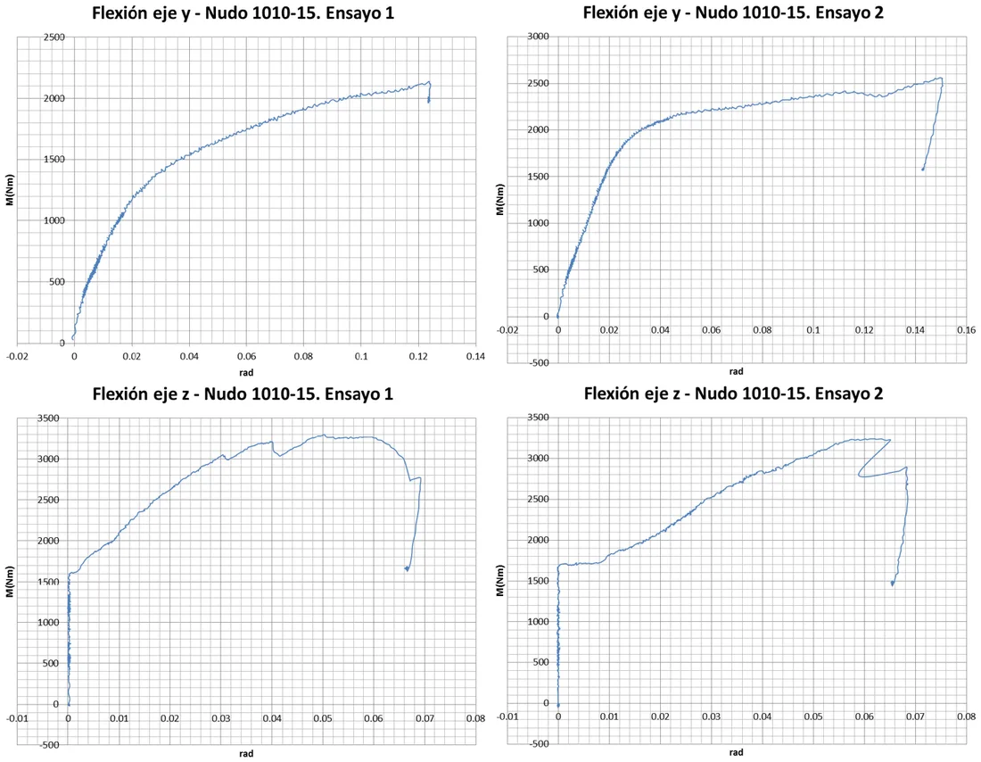
1010-15Bending My / Mz2.14 / 3.30 kN·m2.56 / 3.24 kN·mdeformation
1010-16Tension30.49 kN34.41 kNtearing of the tube
1010-17Tension49.33 kN40.42 kNtearing of the tube
1010-19Tension49.99 kN53.14 kNdeformation of the tube
1010-19Bending My / Mz4.07 / 4.89 kN·m2.93 / 4.68 kN·mdeformation
1010-21Tension72.75 kN71.88 kNshear of the fasteners
1010-21Bending My3.59 kN·m3.65 kN·mdeformation of the tube

Fasteners and bracing

Joint fasteners, self-drilling screws and tensioners

Fasteners by series

Finned joints are supplied with their own fasteners, self-locking serrated and grade 8.8: a DIN 6921 serrated hex flange bolt to fix the joint to the tube, a DIN 931 part-threaded hex bolt as the through-bolt at hinges and pitched connections (with its nut) and a DIN 6923 serrated hex flange nut, one per bolt.

SeriesTube (mm)Fixing to the tubeThrough-bolt (hinges and pitches)Nut
005550×50, finnedM8×20 DIN 6921M8×70 DIN 931M8 DIN 6923
1010100×100, finnedM10×25 DIN 6921M10×120 DIN 931M10 DIN 6923
0105100×50, finnedM10×25 DIN 6921M10×120 DIN 931 · M8×70 (0105-14, -16, -17)M10 / M8 DIN 6923
0510100×100 + 100×50, finnedM10×25 DIN 6921M8×70 / M10×120 DIN 931M8 / M10 DIN 6923
SL2525×25, no finsSupplied without fasteners
SL5550×50, no finsSupplied without fasteners

Examples: 1010-07 (pitched T) comes with 4 M10×25 bolts, 1 M10×120 through-bolt and 5 M10 nuts; the 0055-01 corner bracket with 6 M8×20 bolts and 6 M8 nuts. The omega pieces (0055-15, 0105-15, 1010-15), the column-to-floor pieces (0055-22, 1010-22) and the REF1325 reinforced foot have no fasteners either. Each joint’s product page gives its quantities.

6.3×25 reinforcing self-drilling screw

The joints are reinforced with 6.3×25 self-drilling screws, which stop the members from separating under tension. Each screw provides 3.40 kN in shear with an additional safety factor of 3. Every joint has at least 2 fasteners on two of its faces, and most have 6 or more.

Diameter (mm)Tension (kN)Shear (kN)
4.89.346.58
5.512.508.95
6.314.459.40

Mechanical strength of the screw (core hardness 390 HV; surface 560 HV).

6.3 screw: sheet thickness (mm)Pull-out resistance (kN)Drilling time (s)
49.852.8
512.303.4
614.503.7

Flat-bar bracing

Bracing is treated as tension-only ties: X-bracing with 40×4 flat bar or rigid tube members, placed in the façades where openings allow.

  • 40×4 flat bar, S275JR steel: NRd = 30.0 kN in tension.
  • Double flat bar 2 × 40×4: NRd = 62.0 kN.
  • The piece joining the tensioners is the 1010-17, with 35.00 kN in tension in the tests, above what the flat bar can take.
  • The bracing piece is fixed to the structure with grade 8.8 M12 bolts.

Bracing tensioners

TensionerM6M8M10M12M16M20M24M30M36
Guaranteed tensile strength (kN)2.353.205.356.6516.6525.3536.6553.3571.65

Indicative spans

Indicative maximum spans with tube and omega sections

Reference spans of the StarModul system with 100×100 tube and 200 mm omega section. They are indicative: every project is calculated.

ElementMax. span (m)Spacing (m)
Roof, tube at one level4.501.90
Roof, tube at one level5.271.39
Roof, tube at 2 levels3.003.00
Roof, tube at 2 levels3.702.15
Roof, tube at 2 levels5.301.50
Roof, omega 2005.361.65
Interior floor, double tube5.271.00
Floor, omega 2006.500.50

For industrial buildings the tube-and-joint system reaches about 12 m span; for larger spans, up to about 20 m, we use bolted IPE steel buildings.

Drag to rotate
Ω200 × 2.0 · depth 189.1 mm · 8.36 kg/m

GRAN OMEGA PURLINS

Gran Omega purlins for roofs and façades

Roof purlins and façade girts are made with the Gran Omega purlin: a cold-formed galvanized steel section with holes every 50 mm that bolts straight onto the frames, with no cleats and no welding.

  • 9 sections, from Ω50 to Ω300 (depth 54 to 280 mm)
  • Holes every 50 mm for M10 grade 8.8 bolts
  • Nested laps at the supports: it works as a continuous beam
  • S350GD steel with Z275 galvanizing and CE marking (EN 1090-1)

See the Gran Omega purlin Ask for a quote

Finite element design (2026)

Bracing and splice joints: IDEA StatiCa check (Eurocode 3)

In 2026 two system joints with SHS 100×100×3 mm tube were checked by calculation with IDEA StatiCa Connection (component-based finite element method, EN 1993-1-8, 1-3, 1-1 and 1-5).

Hinged bracing joint

Two SHS 100×100×3 sections (S250) at 45° or 90°, with grade 8.8 fasteners. Maximum resistance for each action on its own (not combined, no moments):

ConfigurationM10 8.8 bolts: axial (kN)Horizontal V (kN)Vertical V (kN)5.5 self-drilling screws: axial (kN)Horizontal V (kN)Vertical V (kN)
45°, 3 bolts per line38.011.015.030.09.212.0
45°, 2 bolts33.010.512.520.08.59.2
45°, 1 bolt18.010.59.210.010.09.2
90°, 3 bolts77.09.211.752.08.511.4
90°, 2 bolts68.09.011.735.08.211.0
90°, 1 bolt33.08.510.011.0–7.9

The reports study 4, 8 and 12 bolts in total per joint (1, 2 or 3 per line). Values valid only for the geometry, materials and layout studied.

Tube splice joint

Splice of two SHS 100×100×3 (S280) with an external 110×110×4 tube sleeve (S235) and 12 grade 8.8 M12 through-bolts (6 per side). Hinged joint (transfers axial and shear forces, not moments).

  • Check under the loads of a real project (industrial building): design load of ±75 kN in tension and compression, with 21.6 % bolt utilisation.
  • Ultimate resistance analysis: load factor of 300 %, i.e. about 225 kN axial in tension or compression.

Failure tests

Joint failure load: tests at the LERMA laboratory (UPC)

The 1010 series joints were tested to failure at the Laboratori d’Elasticitat i Resistència de Materials (LERMA) of the Universitat Politècnica de Catalunya in two campaigns: May 2017 (reports 46009) and October 2018 (reports 47008). Each test used two 100×100×2 mm tube specimens loaded to failure with a 100 kN load cell.

Each test has its load-displacement curve (tension and compression) or moment-rotation curve (bending about the y and z axes). These are the curves for each joint (click to enlarge).
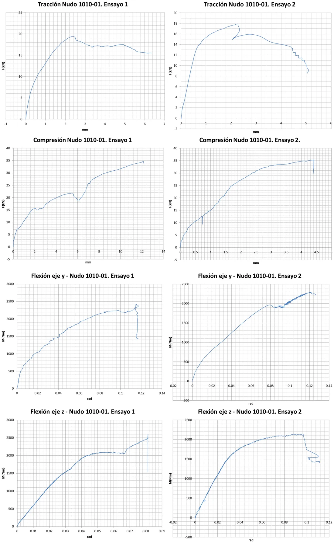
Failure test curves of starmodul joint 1010-01
Joint 1010-01
Failure test curves of starmodul joint 1010-02
Joint 1010-02
Failure test curves of starmodul joint 1010-03
Joint 1010-03
Failure test curves of starmodul joint 1010-05
Joint 1010-05
Failure test curves of starmodul joint 1010-06
Joint 1010-06
Failure test curves of starmodul joint 1010-07
Joint 1010-07
Failure test curves of starmodul joint 1010-11
Joint 1010-11
Failure test curves of starmodul joint 1010-13
Joint 1010-13
Failure test curves of starmodul joint 1010-14
Joint 1010-14
Failure test curves of starmodul joint 1010-15
Joint 1010-15
Failure test curves of starmodul joint 1010-16
Joint 1010-16
Failure test curves of starmodul joint 1010-17
Joint 1010-17
Failure test curves of starmodul joint 1010-19
Joint 1010-19
Failure test curves of starmodul joint 1010-21
Joint 1010-21

Real projects

StarModul structures on site

Some structures calculated and built with the bolted joint system. Click a photo to enlarge it.
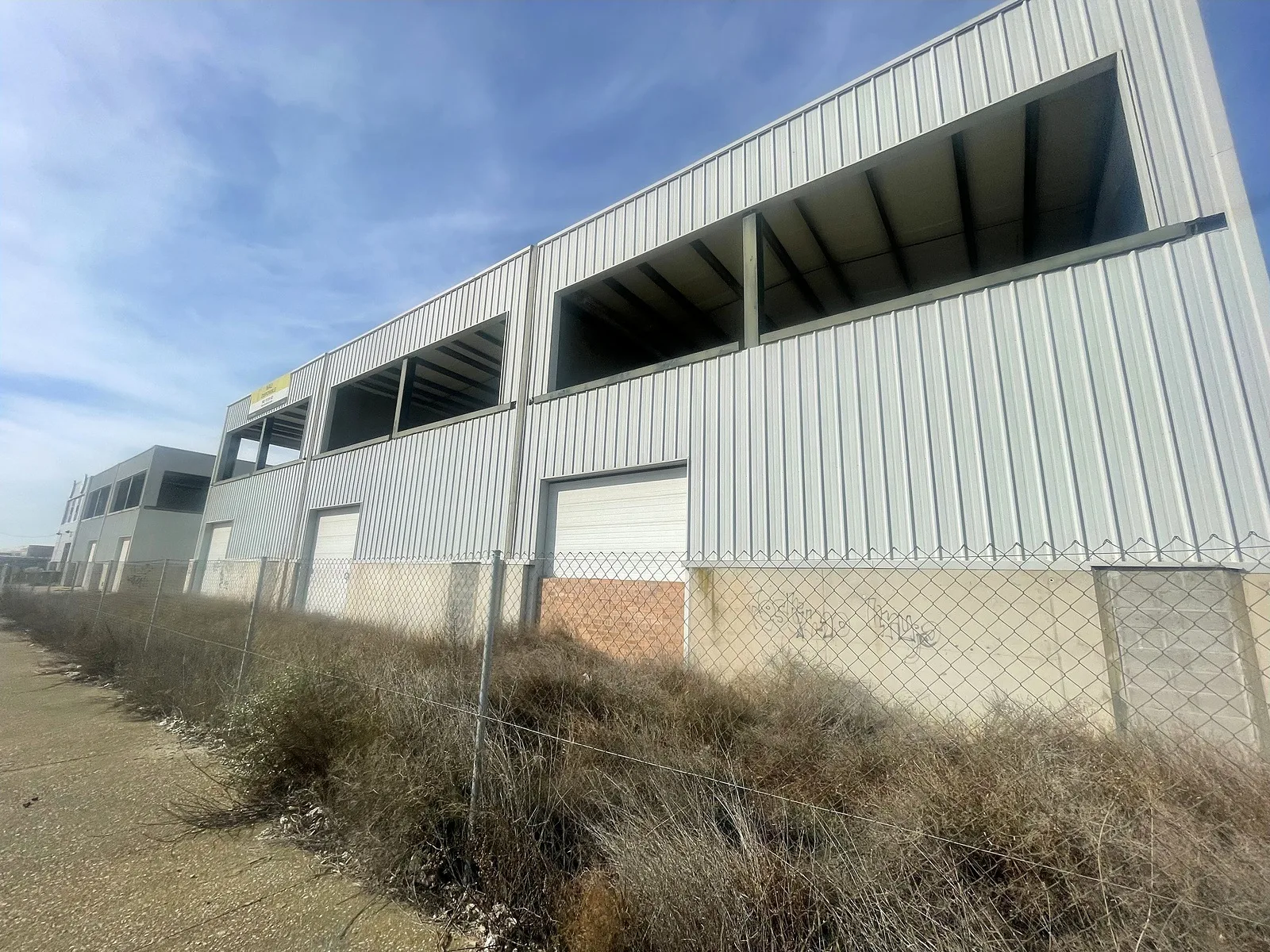
Starmodul bolted steel structure: building under construction (lleida)
Building under construction (Lleida)
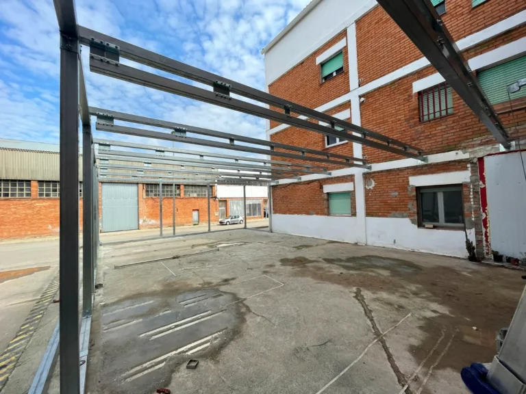
Starmodul bolted steel structure: office extension
Office extension
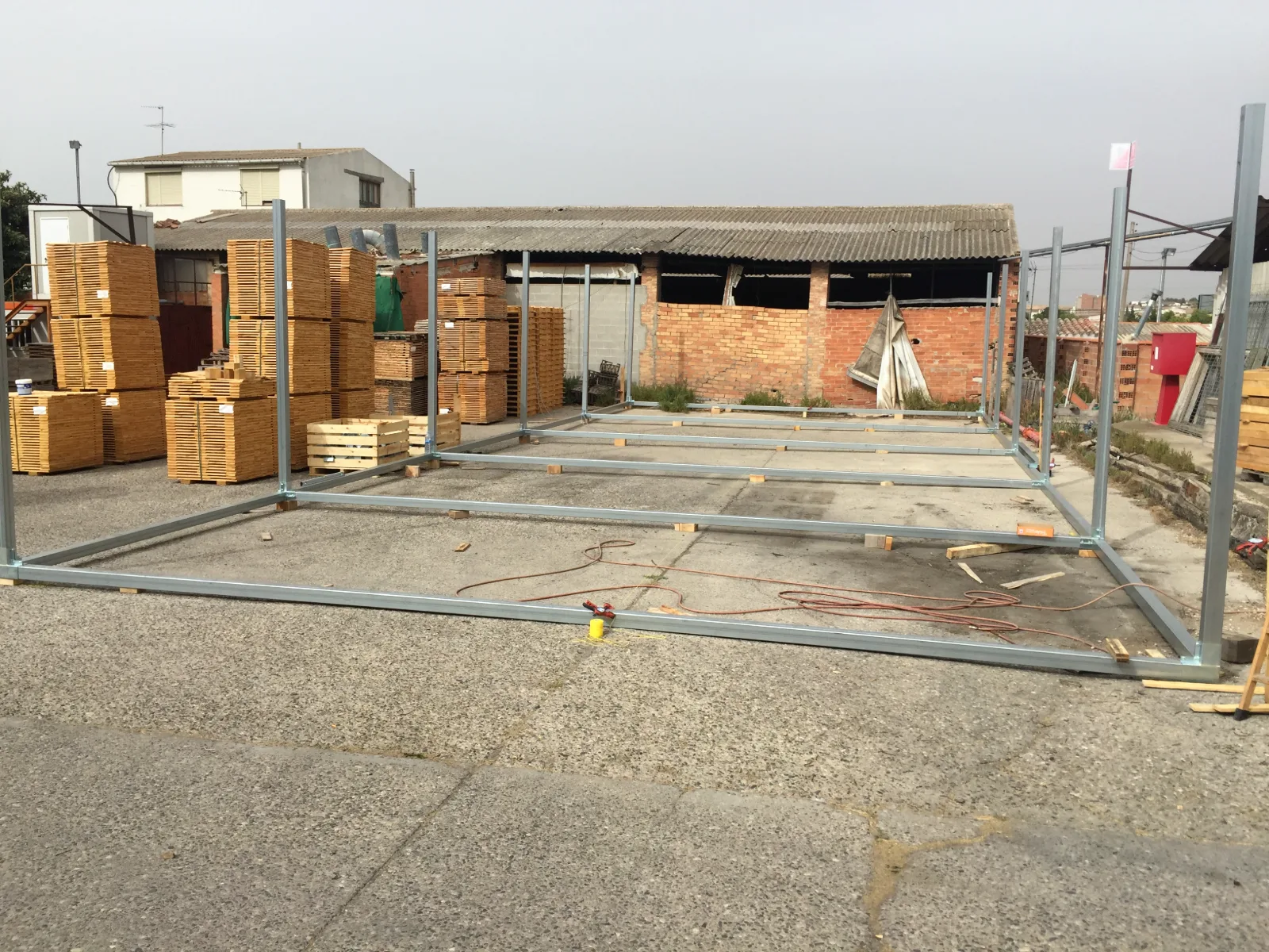
Starmodul bolted steel structure: demountable tube structure
Demountable tube structure
Starmodul bolted steel structure: assembled structure (faura)
Assembled structure (Faura)
Starmodul bolted steel structure: assembled structure (llívia)
Assembled structure (Llívia)
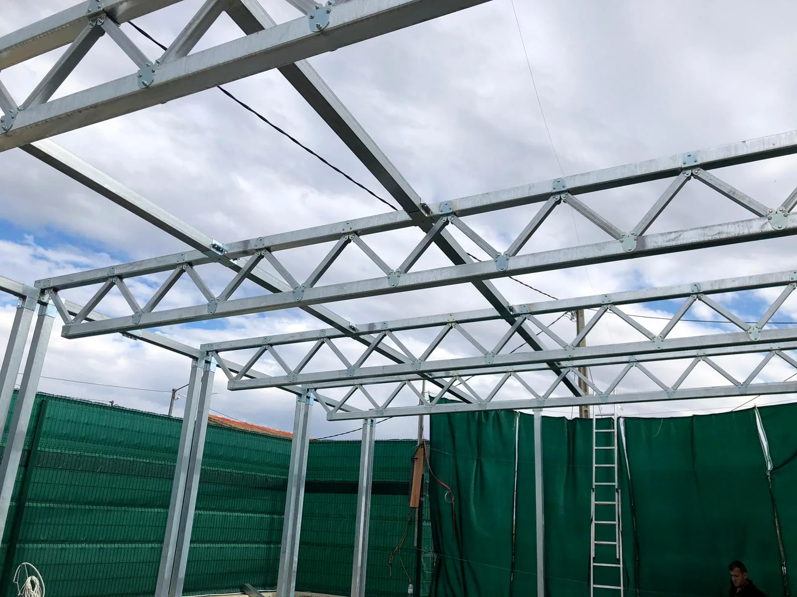
Starmodul bolted steel structure: bolted tube trusses
Bolted tube trusses
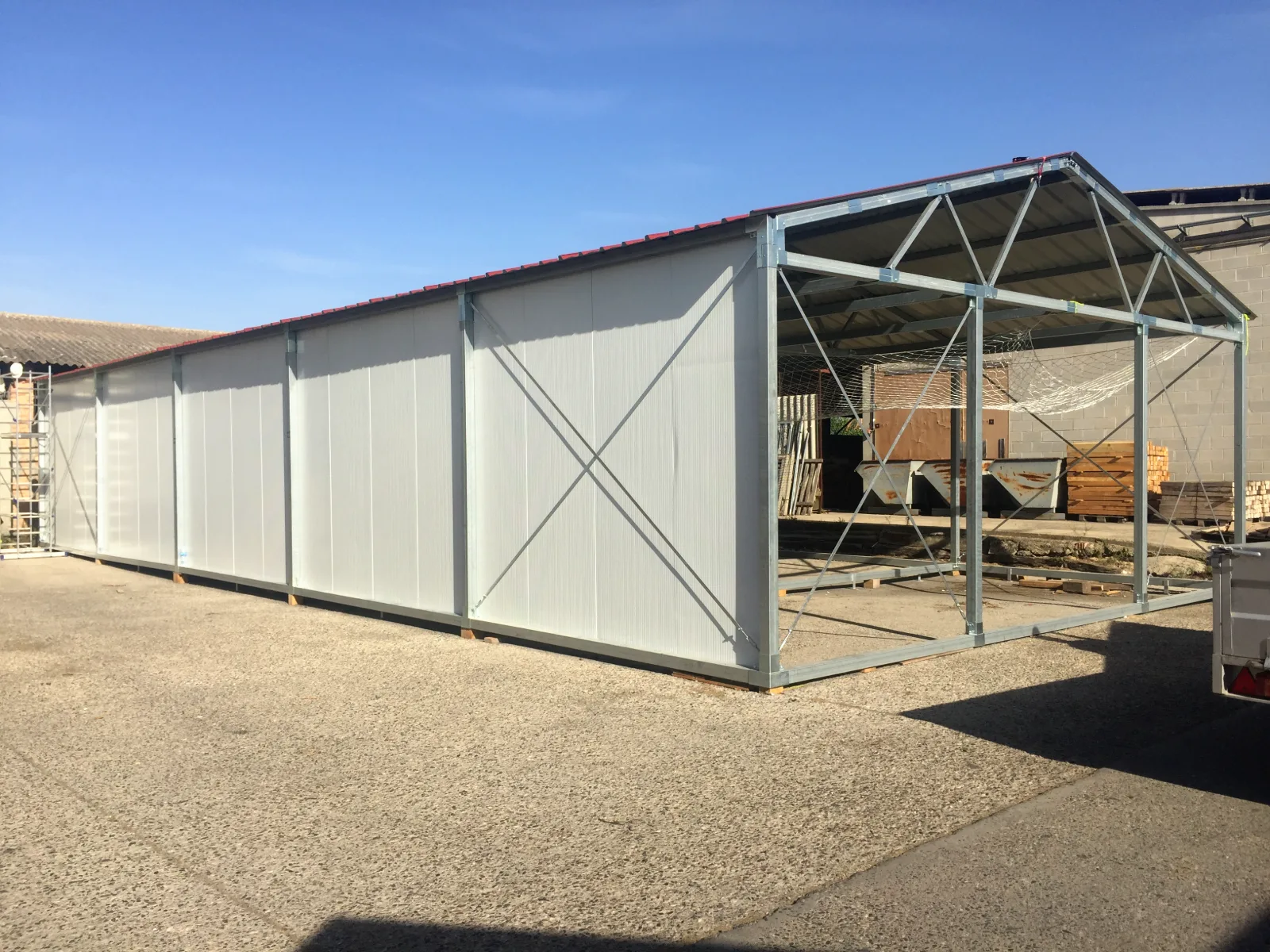
Starmodul bolted steel structure: building with sandwich panels (faura)
Building with sandwich panels (Faura)
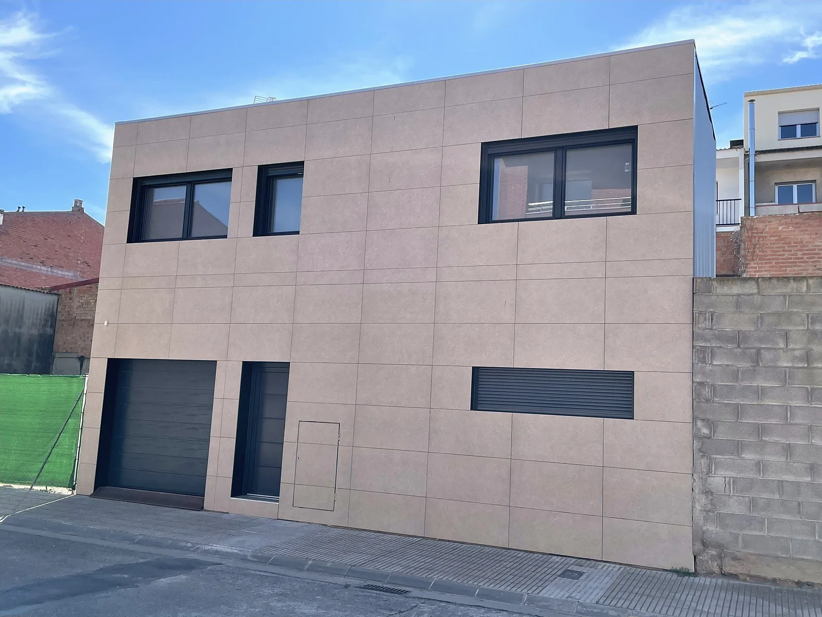
Starmodul bolted steel structure: two-storey house (mollerussa)
Two-storey house (Mollerussa)

Examples and documents

Structural calculation examples and documents

With every quote we send the document “Basic data for structural design with the StarModul system”. For projects that need a calculation (houses, industrial buildings, other buildings), our engineer prepares the calculation report and structural drawings, quoted separately.

Basic data for structural design

The document we include with every quote: materials, reference loads and test values of the 1010 series joints.

PDF · 9 pages · 0.8 MB (in Spanish)

Single-storey detached house (Alicante, 2024)

Real calculation report (codes, actions, 3D model, checks) and structural drawings.

PDF · 118 pages + 7 sheets · 3.2 MB (in Spanish)

IPE steel buildings (Torre-serona and Gabon)

Calculation drawings of two bolted IPE portal-frame buildings. View

PDF · 6 + 8 sheets · 4.2 MB

StarModul general catalogue

Joints, tubes, applications and projects of the system. View

PDF · 47 pages · 4.5 MB (in Spanish)

Real documents: client, site and engineer details have been removed.

Frequently asked questions

Questions about joint design

Are the table values allowable loads?

No. They are failure loads measured in laboratory tests with 100×100×2 mm tube and are indicative. The engineer of each project applies the safety factors and the applicable codes.

Do you do the structural calculation?

Yes. StarModul manages it with its engineer and quotes it separately: it is not included in the price of the kit or the joints.

What bolts does each joint use?

Finned joints come with self-locking serrated grade 8.8 fasteners: a DIN 6921 serrated hex flange bolt, a DIN 931 part-threaded through-bolt at hinges and pitched connections and a DIN 6923 serrated hex flange nut. M8 (M8×20 and M8×70) in the 0055 series and M10 (M10×25 and M10×120) in the 1010, 0105 and 0510 series. Joints without fins (SL25 and SL55) are supplied without fasteners. Calculated structures also use M10 or M12 grade 8.8 bolts and 6.3×25 self-drilling reinforcement screws.

Where can I download the calculation examples?

On this page, under “Structural calculation examples and documents”. The IPE building drawings are also on the IPE buildings page.

Structural design

Need your structure calculated? We handle it

Send us your project or dimensions: our engineer calculates the structure with StarModul joints and we quote it separately. Phone and WhatsApp +34 699 147 762.