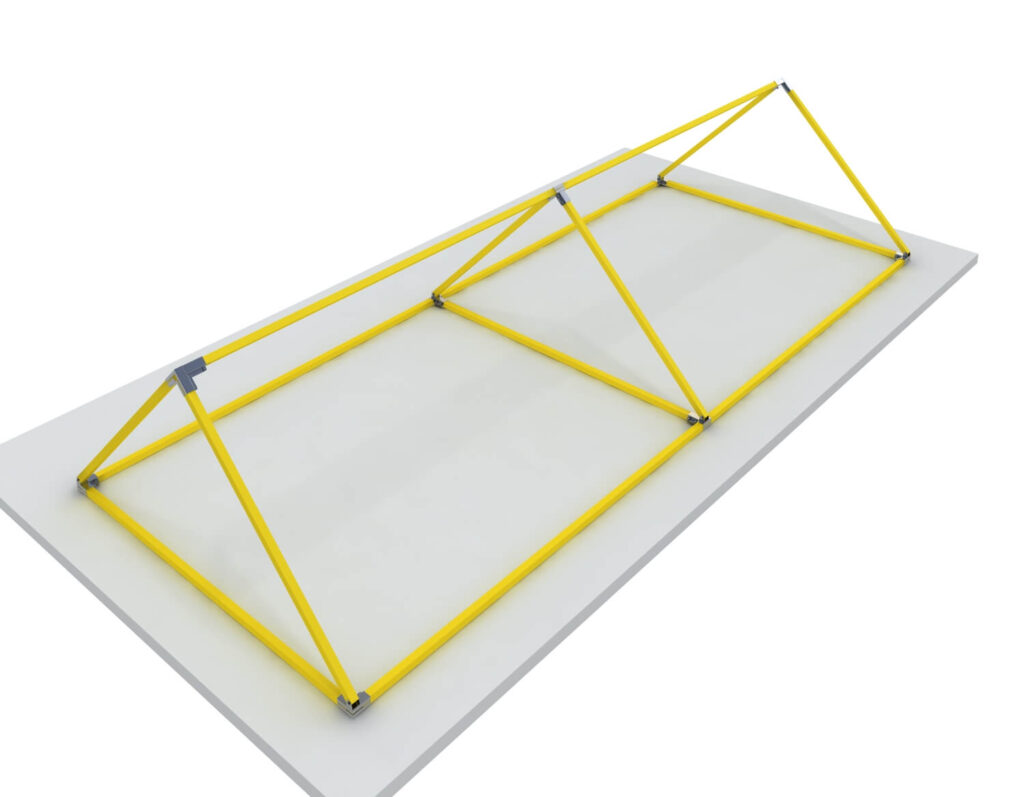
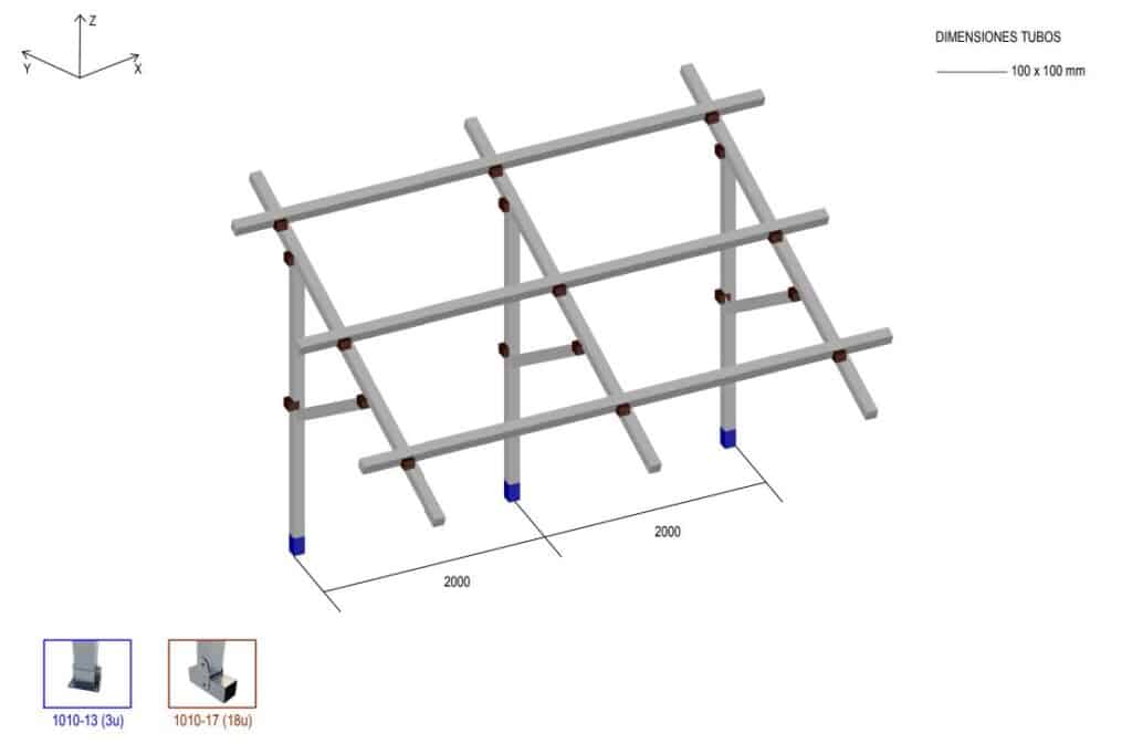
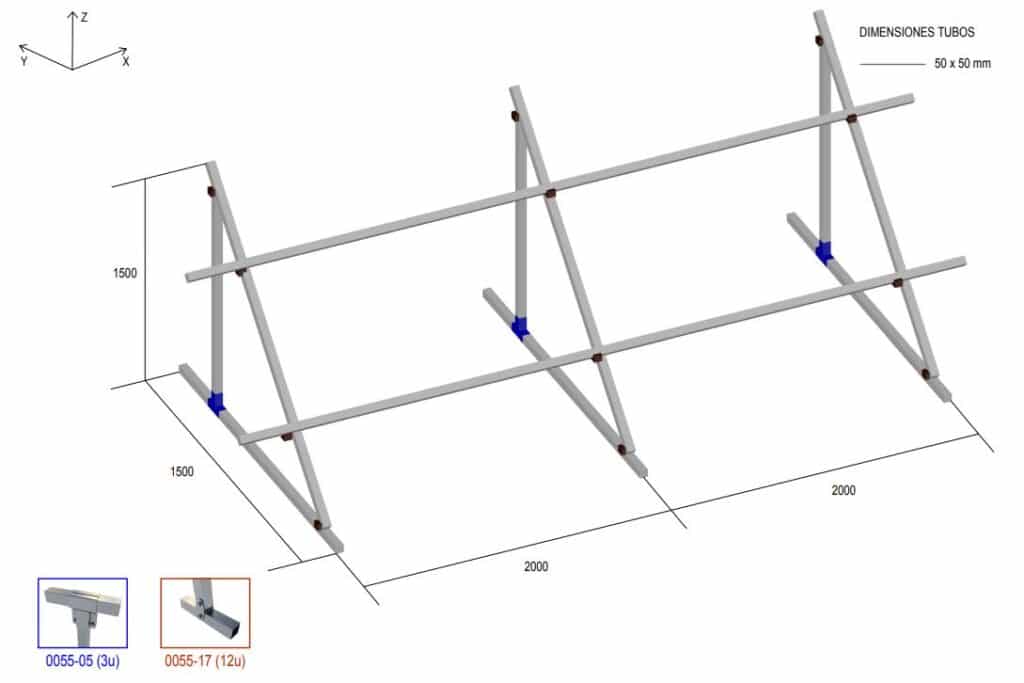
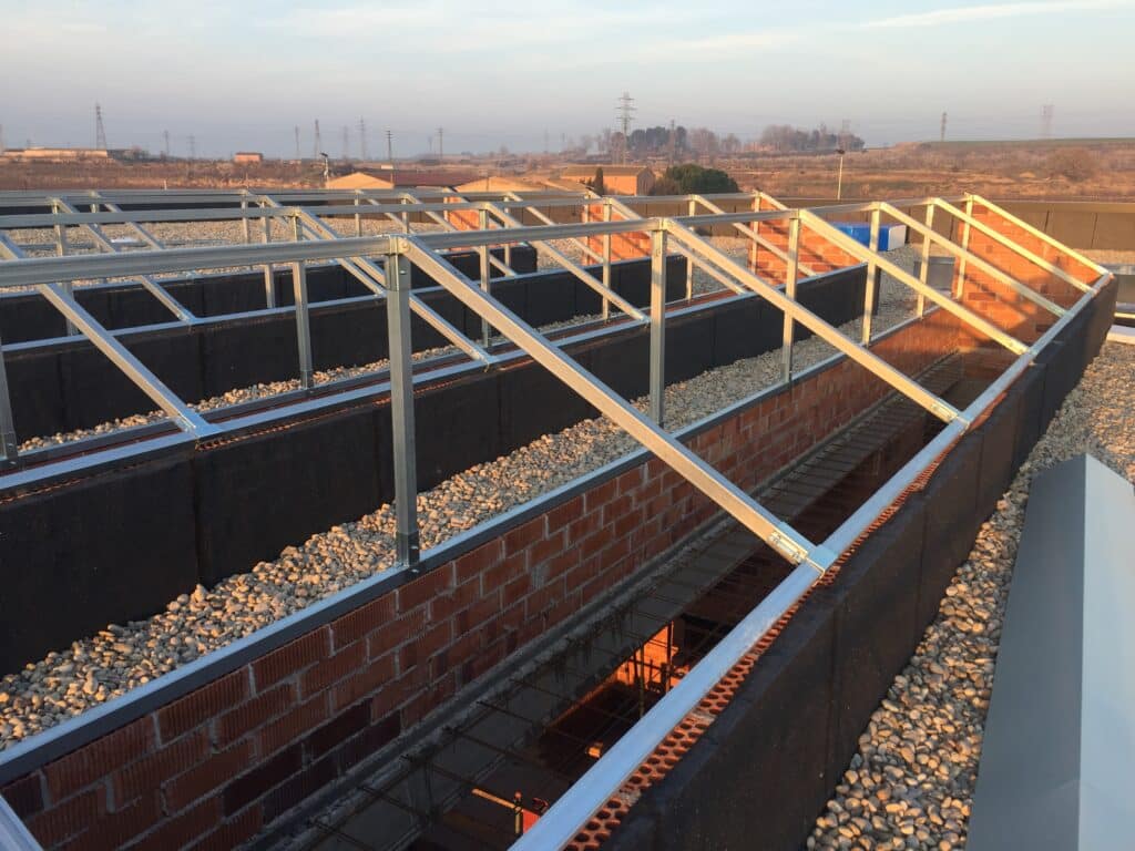
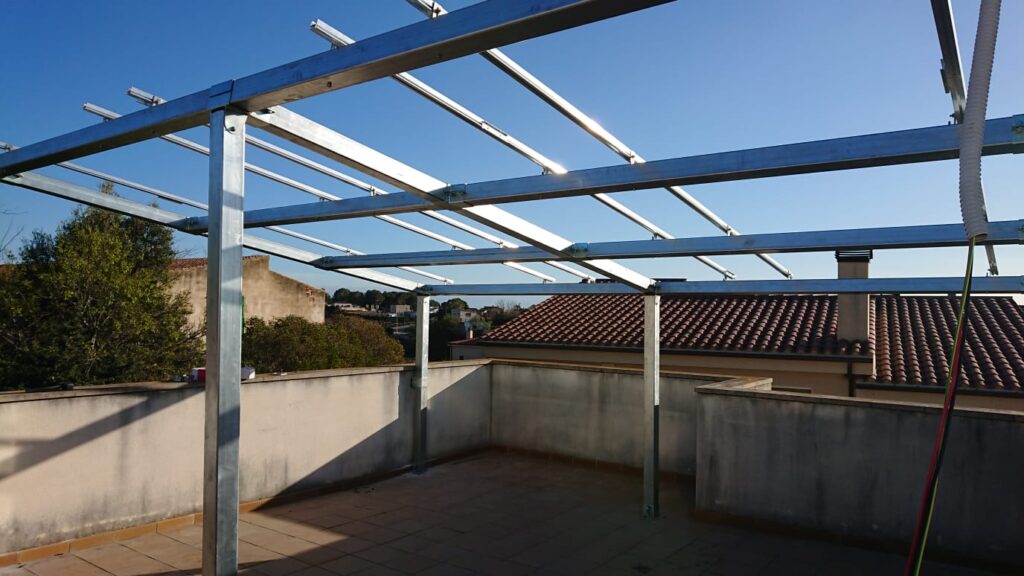
We design metal structures for solar panels using steel profiles and StarModul bolted connections. Each mounting system is tailored to the number and size of the modules, the tilt angle, the layout, the loads, and the site conditions.
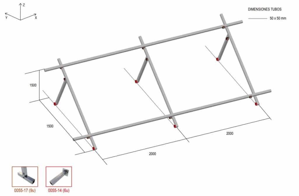
The StarModul system allows you to configure frames, trusses, and substructures using prefabricated profiles and mechanical connections. The geometry is defined to support the panels and properly transfer loads to the supports.
Profiles, thicknesses, and reinforcements determined by calculation.
Screwed joints at compatible joints.
Adaptation to the number of rows, dimensions, and angle of the panels.
Coordination with anchors, foundations, and the photovoltaic system.
ADVANTAGES
Advantages of StarModul Structures for Solar Panels
Screw-type mounting
Compatible joints are assembled using fasteners, reducing the need for welding during assembly.
Adaptive Geometry
Heights, clearances, row spacing, and slopes are adjusted to suit the photovoltaic system.
Calculation by Project
The structure is designed based on its location, geometry, and the effects of wind, snow, and maintenance.
Preliminary Preparation
Profiles and components can be prepared and labeled before arriving at the job site.
Outdoor use
Steel protection is specified based on environmental exposure and the required durability.
Custom Solution
Ground mounts, solar canopies, and auxiliary structures tailored to each installation.
APPLICATIONS
Structures for photovoltaic installations of various types
Support structures can be designed for self-consumption, industrial installations, solar parking lots, or ground-mounted projects. The final solution is coordinated with the photovoltaic design and the structural design.
ON-SITE INSTALLATIONS
Structures for ground-mounted solar panels
For ground-mounted installations, rows of supports can be configured with the height, spacing, and tilt specified in the project. The structure transfers the loads to foundations or anchors designed for the site.
Distribution by rows or modular sets.
Tilt coordinated with the solar study.
Areas designated for assembly and maintenance.
Anchors and supports specified based on the terrain and loads.
PHOTOVOLTAIC CANOPIES
Parking lots and carports with solar panels
A photovoltaic canopy uses the roof to generate energy while also protecting vehicles or walkways. The design must take into account clearances, columns, water drainage, and the layout of the modules.
Company and store parking lots.
Carports for homes and communities.
Charging stations for electric vehicles.
Solutions for one or more seats.
ROOFS AND AUXILIARY STRUCTURES
Photovoltaic Mounting Systems for Roofs and Industrial Spaces
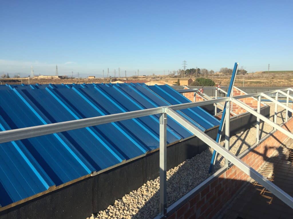
Substructures or auxiliary frames can also be considered for installing panels on roofs, patios, or industrial facilities. Before making any changes to an existing building, its load-bearing capacity and fastening system must be verified.
Elevated or sloped substructures.
Expansions of existing facilities.
Freestanding supports next to buildings.
Integration is contingent upon a review of the existing structure.
STRUCTURE CONFIGURATION
What Defines a Metal Frame for Solar Panels
1 · Implementation
Number, format, and layout of the planned photovoltaic modules.
2 · Geometry
Slope, orientation, heights, spans, and required spacing between rows.
3 · Structure
Profiles, thicknesses, reinforcements, and connections defined by structural analysis.
4 · Support
Anchors or foundations designed to integrate with the ground, the roof, or the existing base.
CALCULATIONS, ANCHORAGES, AND DURABILITY
A solution tailored to specific loads and site conditions
Stability does not depend solely on the weight of the panels. The calculation must take into account wind, suction, snow, maintenance, geometry, and the type of support. Therefore, a standard foundation or anchor should not be selected without first reviewing the actual conditions of the project.
Wind and snow loads, and maintenance loads.
Characteristics of the site or the existing structure.
Necessary fasteners, base plates, and foundations.
Corrosion protection based on the exposure environment.
HOW WE WORK
From Photovoltaic Design to Structural Assembly
1 · Initial Data
Location, layout, number of panels, dimensions, orientation, and type of installation.
2 · Design and Calculations
The geometry, profiles, supports, reinforcements, and necessary connections are defined.
3 · Preparation
The components are prepared, machined, and labeled in accordance with the documentation.
4 · Assembly
The structure is laid out, assembled, and coordinated with the installation of the panels.
PROJECTS
StarModul Structures for Solar Installations
Examples of metal supports, frames, and structures for various photovoltaic configurations.
Use the StarModul 3D configurator to create an initial geometry and obtain preliminary information on profiles and connections. The configuration must be reviewed and sized for the actual loads of the project.
Steel sections are used in configurations such as frames, trusses, or substructures. In StarModul, compatible nodes are connected using bolted joints, and the sections, thicknesses, and reinforcements are defined for each project.
It must be sized to withstand the loads applicable at its location, including wind, suction, snow, dead load, and maintenance loads. Its strength is verified through the project’s structural analysis.
Components compatible with the StarModul system are assembled using mechanical fasteners and screws. Anchors, foundations, or other special elements are designed according to the project specifications.
The slope is determined based on the photovoltaic design, orientation, row spacing, and site conditions. The structural geometry is then adapted to these parameters and verified through calculations.
There is no single figure: it depends on the module format, layout, spans, height, and loads. The solution is configured and sized based on the planned number of panels.
The scope is defined in each bid. The metal structure must be coordinated with the photovoltaic supplier regarding module mountings, wiring, inverters, and other electrical components.